As an automation engineer it is important to know about the industrial communication protocols. When I wanted to learn protocols and networking I ended up reading about OSI model and this is the best starting point. Whoever wants to learn basic networking should end up learning the OSI model which we have overlooked during engineering course. OSI model was developed by ISO to standardize how devices can communicate data in a network. In general all text books shows below Fig(1) to explain the model, but I found it difficult to associate it with real time usage. So I am compiling from various sources which I read and will try to explain as per my understanding to fit the model with practical world. If any mistakes are there, I welcome healthy discussions and comments to correct what I have written.
Fig(1). OSI model
When a device transmits data, it is broken in to pieces and wrapped with additional data before transmitted in to the network. This will help the device on receiving end to reconstruct the message or data and process it accordingly. Each layer of the OSI model contributes at various stages. Layer wise explanation as below.
Application layer:
This layer is the direct interface between the user and network. All the protocols such as HTTP, FTP, DNS, etc. operates in this level. Example when an URL is requested from address bar of the browser, the request is converted as a http/ https request and that request message is sent to next layer. On the other end of the network the Application will interpret the request and responds accordingly.
Data in this layer is called message.
Presentation layer:
This layer is a translation layer. It performs encoding/ decoding/ compressing the application layer data before sending in to the network. On receiving end it will make meaning full message out of the data it received from below layers. This message is further displayed or processed by the application layer.
Data in this layer is called message.
Session layer:
When a device tries to connect with another device a session is created and all transaction happen between the devices will be through the corresponding session. Windows uses socket method (winsock) to establish this session. First a open connection request is sent by client. Then server sends an connection acceptance reply. And to finish connection an acknowledgment is sent again by client. If a session breaks a reset message is sent and synchronization happens again. This is the layer which manages the connectivity between the devices.
Data in this layer is called message.
Transport layer:
There is limitation on how much data can be sent over a packet, hence this layer will break the message sent by presentation layer in to pieces called segments. To identify the segment's position in the message, a sequential number will be attached with the message. On receiving end, this layer will rearrange the frames in to a complete message using the segment ID so that the presentation layer can process it. If the received data are incorrect or missing any segment, it will request a resend. If server fails to receive the acknowledgement, it will transmit the data again.
TCP and UDP operates here through ports. Every transaction happens through ports. Example TCP operates using server/ client model. The device which initiates the connectivity is called client (master) and which are being connected with are called server (slave). Server can't initiate any communication and will serve only the query sent by client. This layer will add a TCP header to the message which comprises details of source and destination port, data checksum, message length, segment number and acknowledgement number. The data correctness is checked with the help of checksum.
Data in this layer is called segment.
Network layer:
This is the layer actually responsible for routing the packets to the intended device. On receiving a packet this layer will filter and decide whether the packet is intended for that particular device, if not the packet is dropped. To decide this, the destination IP address in the packet is checked. Protocols such as ARP, RARP, IP, etc operates in this layer. The segments from the previous layer are attached with an IP header and sent out as packets. The IP header will have details such as source and destination IP address, version of the IP used (IPv4 or IPv6), length of the header, length of the actual packet, type of protocol, header checksum and actual data. When it comes for how IP addressing works, lot of other details such as subnet mask, IP class, etc comes in. Those are for other topic.
Data in this layer is called packet.
Data link layer:
Data link layer work based on actual device address (kind of permanent unique address) called MAC address. MAC address is entirely different from IP address. The IP address is a 32 bit - 4 octet number. It changes whenever the device connects to a network. But the MAC address is a permanent one and assigned by the device manufacturer. Its a 48 bit address with first 3 bytes representing manufacturer number and last 3 bytes represent that device number.
Same like network layer, this layer also accepts the frames to be processed if the frame is relevant to that particular device. Only difference is network layer uses IP address but data link layer used MAC address to filter the packets.
While receiving the frame, the frame is filtered and then the data link header is removed before sending to the network layer. Similarly while sending the packet the data link layer header is added to the packet and sent out to the network. The header have details such as source and destination MAC address. At the end of the frame a CRC checksum is attached.
Data in this layer is called frame.
Physical layer:
Physical layer is the physical medium over which the device is connected. The physical mediums can be CAT-6 cable, fiber optic cable, etc.
Data in this layer are bits.
Summary:
The OSI model is just a guideline to follow. When it comes for practical world the difference between the layers become very thin and neglected. As seen in the below Fig(2), the differentiation between application layer, presentation layer and session layer were neglected and merged. In TCP/IP model these three layers are collectively called as application layer. Similarly the datalink layer and physical layer are merged as network access layer.
Fig(2)
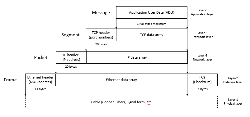
While sending a message to network, every layer adds a header and checksum so that it will be helpful for the receiving device to process the packet. Similarly on receiving the packets respective layers removes the associated header before sending to the next layer. Refer below fig(3) for better understanding a pictorial representation of data flow from top application layer to bottom physical layer.

Fig(3). Data flow through layers


No comments:
Post a Comment